Oxford Revise AQA A Level Physics | Chapter P16 answers
P16: Capacitance
|
Questions |
Answers |
Extra information |
Mark |
AO |
Spec reference |
||||||||||||||||||||||||||||||||
|
01.1 |
\( \begin{array}{lll} Q & = & CV = 1000 \times 10^{-6} \times 12 = 1.2 \times 10^{-2}\textrm{ C}\\ I & = & \frac{V}{R} = \frac{12\ \rm{V}}{2400\ \Omega} = 5.0 \times 10^{-3}\textrm{ A}\\ \end{array} \) |
1 |
2 |
3.7.4.2 |
|||||||||||||||||||||||||||||||||
|
01.2 |
Time for p.d. to drop to half its value = RC ln2 = 2400 × 1000 × 10−6 × 0.693 = 1.67 s
|
Graph with scales/labelled axes extending to 6 seconds Initial p.d. = 12 V and exponential shape by eye Evidence for p.d. halving in 1.7 s |
1 |
2 |
3.7.4.4 |
||||||||||||||||||||||||||||||||
|
01.3 |
Original time constant = RC = 2400 × 1000 × 10–6 = 2.4 s New time constant = 1.8 × 2.4 = 4.32 s Effective capacitance = \(\frac{{4.32}}{2400}\) = 1.8 × 10⁻³ F Capacitances in parallel add so Ctotal = C + 1000 × 10-6 F = 1.8 × 10⁻³ F C = 0.8 × 10⁻³ F = 800 μ F |
Calculation of new time constant/method involving time constant Answer |
|
3 |
3.7.4.4 |
||||||||||||||||||||||||||||||||
|
01.4 |
Assumption is that the voltmeter has infinite resistance If the voltmeter has a large but finite resistance, this reduces the resistance of the circuit because there are now two resistances in parallel The time constant will be smaller than it should be, so the unknown capacitance is larger than the value in 06.3 |
Effect of resistance of voltmeter on resistance of circuit Effect on capacitance |
1 |
1 |
3.7.4.4 |
||||||||||||||||||||||||||||||||
|
02.1 |
From the graph, the time for the p.d. to halve 0.12 ms Time to halve = RC ln2 \(\begin{array}{lll} \textrm{Time constant } = RC & = & \frac{\textrm{(time to halve)}}{0.693}\\ & = & 1.73 \times 10^{-4}\textrm{ s}\\ \end{array} \) |
Use of graph to find time to halve Answer |
1 |
2 |
3.7.4.4 |
||||||||||||||||||||||||||||||||
|
02.2 |
\( \begin{array}{lll} \textrm{C} & = & \frac{\textrm{time constant}}{R}\\ & = & \frac{2.89 \times 10^{-4}}{10 \times 10^3}\\ & = & 2.89 \times 10^{-8}\textrm{ F}\\ \end{array} \) |
Use of time constant to find C |
1 |
2 |
3.7.4.4 |
||||||||||||||||||||||||||||||||
|
02.3 |
Curve that starts at half the p.d. on the y-axis, and has T½ that is double the original value by eye If the resistance doubles, the maximum current will halve, so the maximum p.d. will halve If the resistance is doubled, the time constant is doubled, so the time to halve the p.d. is also doubled |
Correct line on graph Explanation of p.d. × \(\frac{1}{2}\) Explanation of time to halve × 2 |
1 |
3 |
3.7.4.4 |
||||||||||||||||||||||||||||||||
|
02.4 |
Use the p.d. and resistance to work out the current using \(I = \frac{V}{R}\) The area under the graph is the charge stored; work out the charge represented by each square using Q = It; count squares and multiply |
Conversion of p.d. to current How to find charge from area |
1 |
3 |
3.7.4.4 |
||||||||||||||||||||||||||||||||
|
03.1 |
When the switch is closed, there is a potential difference across the resistor A current flows, so the charge on the capacitor decreases As the charge decreases, the p.d. decreases \((V = \frac{Q}{C}),\) so the current decreases in the same way The rate of change of p.d. depends on the charge, and hence p.d., so the relationship is a negative exponential |
Link between p.d. and current Link to charge on capacitor Explanation of exponential |
1 |
1 |
3.7.4.2 |
||||||||||||||||||||||||||||||||
|
03.2 |
|
Calculations of t in seconds and lnV do not penalise excessive significant figures Graph starting at (0, 0), points plotted, linear line of best fit Correct labels/units |
1 |
2 |
3.7.4.4 |
||||||||||||||||||||||||||||||||
|
03.3 |
\( \begin{array}{lr} V = {V_0}e^{-\;\frac{t}{RC}}\\ \ln \ V = \ln \ V_0 – \frac{t}{RC}\\ \textrm{So a graph of ln } V\textrm{ against } t\\ \textrm{gradient } = -\frac{1}{RC}\\ \end{array} \) |
Taking natural logs of both sides of equation Gradient correct |
1 |
2 |
3.7.4.4 |
||||||||||||||||||||||||||||||||
|
03.4 |
ln(1.5) = 0.405 Reading from graph when ln V = 0.4, t = 700 s = 11 minutes and 40s |
Correct deduction from graph |
1 |
2 |
3.7.4.4 |
||||||||||||||||||||||||||||||||
|
04.1 |
\( \begin{array}{lll} E & = & \frac{1}{2}CV^2\\ & = & \frac{1}{2} \times 470 \times 10^{-6} \times (6.0)^{2}\\ & = & 8.46 \times 10^{-3}\textrm{ J} = 8.5 \times 10^{-3}\textrm{ J}\\ \end{array} \) |
Answer |
1 |
2 |
3.7.4.3 |
||||||||||||||||||||||||||||||||
|
04.2 |
\(\textrm{Resistance of lamp } = \frac{6.0}{0.3} = 20\ \Omega\)
Time to discharge to 37% = RC = 470 × 10-6 × 20 = 9.4 × 10⁻³ s energy transferred = \(8.46 \times {10^{-3}} \times {0.37^2} = 1.158 \times 10^{-3}\ \rm{J}\) \(\textrm{power} = \frac{\textrm{energy}}{\textrm{time}} = \frac{1.158 \times 10^{-3}}{9.4 \times 10^{-3}} = 0.12\ \textrm{W}\) You may not see this as it is less than a tenth of the bulbs normal power rating power = 6 V × 0.3 A = 1.8 W |
Calculation of resistance Explicit use of RC as time for p.d. to reduce to 37% energy transferred from capacitor ∝ V2 Calculation of power Appropriate comment with numerical comparison |
1 |
3 |
3.7.4.3 |
||||||||||||||||||||||||||||||||
|
04.3 |
The energy stored would be multiplied by 4 as energy stored depends on V2 The time is the same Power would be multiplied by 4; this would definitely be observable but still dim |
Reference to E proportional to V2 Effect on what is observed / appropriate comment |
1 |
3 |
3.7.4.3 |
||||||||||||||||||||||||||||||||
|
04.4 |
(use of \(E = \frac{1}{2}C{V^2}\)) \(\rm{470\ \mu F\ capacitor\ would\ need\ a\ p.d.\ of\ }V = \sqrt { \frac{2E}{C} } = 650\ \textrm{V}\)a 6 V p.d. would need a capacitance of \(C = \frac{E}{{2{V^2}}} = 1.4\textrm{ F}\) 1.4 F is a very large capacitor, so the energy stored is achieve by increasing the p.d. |
Comment on size of capacitance |
|
3 |
3.7.4.3 |
||||||||||||||||||||||||||||||||
|
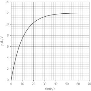
05.1 |
Initially there is no charge on the capacitor, so zero p.d.; as the capacitor charges the p.d. increases as \(V = \frac{Q}{C}\) And increases at a decreasing rate |
Exponential growth by eye Asymptotic to 12 V Only a sketch needed, so no values needed on x-axis Correct description of V proportional to charge Comment about shape |
1 |
1 |
3.7.4.4 |
||||||||||||||||||||||||||||||||
|
05.2 |
Reducing the resistance; as the current normally decreases as the capacitor charges, a smaller resistance is needed to maintain the current at a constant value The graph will be a straight line through (0, 0) as the p.d. increases at a constant rate The graph will be horizontal when the capacitor is fully charged |
Answer and reason needed for mark |
1 |
3 |
3.7.4.4 |
||||||||||||||||||||||||||||||||
|
05.3 |
Procedure described, for example:
|
Sufficient detail Using the graph to find the time Calculating charge from current and time Repetition/finding mean |
|
1 |
3.7.4.4 |
||||||||||||||||||||||||||||||||
|
05.4 |
Appropriate suggestion and solution, for example: The reading on the ammeter will not be constant as it will be difficult to change the resistance to exactly match the exponential decay of current Repeating the experiment many more times will give a more accurate measurement |
1 |
1 |
3.7.4.4 |
|||||||||||||||||||||||||||||||||
|
06.1 |
The water molecule aligns with the electric field between the plates so that the positive side of the molecule (H+) is attracted to the negative plate, and the negative side (O–) is attracted to the positive plate |
Movement of molecule to align with field |
1 |
2 |
3.7.4.2 |
||||||||||||||||||||||||||||||||
|
06.2 |
The greater the humidity, the greater the capacitance The water molecules effectively reduce the distance between the plates of the capacitor, and \(C = \frac{{A{\varepsilon_0}{\varepsilon_r}A}}{d},\) C is inversely proportional to d, so as d decreases, C increases |
Relationship Effect of water molecules on distance Link to capacitance |
1 |
3 |
3.7.4.2 |
||||||||||||||||||||||||||||||||
|
06.3 |
|