Oxford Revise AQA A Level Physics | Chapter P30 answers
P30: Analogue and digital signals
|
Question |
Answers |
Extra information |
Mark |
AO |
Spec reference |
||||||||||||||||||||||||||||||||||||||||||||||||||||||
|
01.1 |
\(\textrm{Time for one sample } = \frac{1}{500} = 0.002\ \rm{s}\)
|
Time for one sample correct Remaining points plotted correctly |
1 |
2 |
3.13.2.1 |
||||||||||||||||||||||||||||||||||||||||||||||||||||||
|
01.2 |
The sampling rate is too low and high-frequency sections of the signal will be lost There will be aliasing (spurious low signals) |
1 |
2 |
3.13.2.1 |
|||||||||||||||||||||||||||||||||||||||||||||||||||||||
|
01.3 |
Number of samples = 3 × 60 × 500 = 90 000 Bits per sample = 4 Total number of bits = 360 000 Number of bytes = 45 000B = 45 kB |
Number of samples Number of bits Answer |
1 |
2 |
3.13.2.1 |
||||||||||||||||||||||||||||||||||||||||||||||||||||||
|
01.4 |
Increase the bits per sample The song would increase the storage space required/take longer to send/download |
1 |
2 |
3.13.2.1 |
|||||||||||||||||||||||||||||||||||||||||||||||||||||||
|
01.5 |
The output of the ADC is in parallel form because each sample contains 4 (simultaneous) bits These bits have to be converted to a serial stream in order to be sent |
1 |
1 |
3.13.2.1 |
|||||||||||||||||||||||||||||||||||||||||||||||||||||||
|
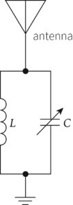
02.1 |
Circuit with capacitor and inductor in parallel Aerial and earth connected at opposite points
|
1 |
1 |
3.13.2.2 |
|||||||||||||||||||||||||||||||||||||||||||||||||||||||
|
02.2 |
\( \begin{array}{l} f_0 = \frac{1}{2\pi \sqrt {LC}}\\ C = \frac{1}{\left( 2\pi f_0 \right)^2 L}\\ =\frac{1}{\left( 2\pi \times 1.1 \times 10^6 \right)^2 \times 2.3 \times 10^{-3}}\\ = 9.1 \times 10^{-12}\ \rm{F} = 9.1\ \rm{pF} \end{array} \) Capacitor A would work |
Substitution Answer Capacitor identified |
1 |
2 |
3.13.2.2 |
||||||||||||||||||||||||||||||||||||||||||||||||||||||
|
02.3 |
\( \begin{array}{l} Q = \frac{f_0}{f_{\rm{B}}}\\ {f_{\rm{B}}} = \frac{f_0}{Q} = \frac{1\,100\,000}{50}\\ = 22\,000\ \rm{Hz} = 22\ \textrm{kHz so the peak at}\ 0.7\ \rm{is}\ 22\ \rm{kHz\ wide}\\ \end{array} \)
|
Bandwidth Peak at 1100 and 1.0 relative gain 22 kHz wide at 0.71 relative gain Approximate shape |
|
2 |
3.13.2.2 |
||||||||||||||||||||||||||||||||||||||||||||||||||||||
|
02.4 |
The mark scheme gives some guidance as to what statements are expected to be seen in a 1 or 2 mark (L1), 3 or 4 mark (L2), and 5 or 6 mark (L3) answer
|
The following statements are likely to be present: Bullet point 1 in question (Analogy between components) 1. The mass is analogous to the inductance 2. The spring constant is analogous to \(\frac{1}{\rm{capacitance}}\) 3. Energy can be stored in the mass–spring system, and in the LC system 4. The mass–spring system oscillates with a characteristic/ natural frequency, and so does the LC circuit 5. Energy can be transferred more easily at low frequencies, but there is increasing resistance to motion as the acceleration, which is analogous to the LC circuit Bullet point 2 in question (Explaining resonant frequency) 5. For a mass–spring system, the time period is \(T = 2\pi \sqrt {\frac{m}{k}}\), so in the LC circuit \(T = 2\pi \sqrt {LC}\) 6. \(f\frac{1}{T}\), so \(f = \frac{1}{{2\pi \sqrt {LC} }}\) 7. When a mass–spring system is forced to oscillate at its natural frequency, it will resonate, so an LC circuit will oscillate when an alternating pd at the natural frequency is applied 8. In a mass–spring system, energy is transferred between being stored kinetically and being stored potentially. In an LC circuit, energy is transferred from being stored in the electric field in the capacitor and the magnetic field of the inductor |
6 |
1 |
3.13.2.2 |
||||||||||||||||||||||||||||||||||||||||||||||||||||||
|
03.1 |
The output depends on the difference between the inputs to the inverting and non-inverting input The gain of a comparator is infinite, but the gain of a difference amplifier can be controlled by the values of the resistors connected to the amplifier |
1 |
1 |
3.13.4.2 |
|||||||||||||||||||||||||||||||||||||||||||||||||||||||
|
03.2 |
If the operational amplifier was being used as a comparator then the output would be ±24 V, and not values in between |
1 |
2 |
3.13.4.2 |
|||||||||||||||||||||||||||||||||||||||||||||||||||||||
|
03.3 |
\( \begin{array}{l} \rm{Gain}\ = \frac{{{V_{{\rm{out}}}}}}{{{V_ + } – {V_ -}}} = 4 = \frac{{{R_{\rm{f}}}}}{{{R_{{\rm{in}}}}}}\\ R_{in} = 4 \times 10\ \rm{k}\Omega = 40\ \rm{k}\Omega \end{array} \) |
1 |
2 |
3.13.4.3 |
|||||||||||||||||||||||||||||||||||||||||||||||||||||||
|
03.4 |
The third electrode ensures that the ‘noise’ picked up by the mains would be the same for each electrode Because the amplifier is amplifying the difference, the noise would not be amplified The only p.d. that is amplified is that produced by differences between the signals produced by the electrodes, making it suitable for detecting irregularities in heart rhythms |
1 |
3 |
3.13.4.3 |
|||||||||||||||||||||||||||||||||||||||||||||||||||||||
|
04.1 |
1101 |
Do not accept 1011 |
1 |
2 |
3.13.2.1 |
||||||||||||||||||||||||||||||||||||||||||||||||||||||
|
04.2 |
\( \begin{array}{l} {V_{{\rm{out}}}} = -10\,{\rm{k}} \times \left( {\frac{5}{{10\,{\rm{k}}}} + \frac{5}{{20\,{\rm{k}}}} + \frac{0}{{40\,{\rm{k}}}} + \frac{5}{{80\,{\rm{k}}}}} \right)\\ = -8.125\ \rm{V} \end{array} \) |
Substitution Answer (must be negative) |
1 |
3.13.4.3 |
|||||||||||||||||||||||||||||||||||||||||||||||||||||||
|
04.3 |
Connect the output to an inverting amplifier to change to a positive value \(\begin{array}{l} \frac{{{V_{{\rm{out}}}}}}{{{V_{{\rm{in}}}}}} = \frac{13}{{-8.125}} = -1.6\\ -\frac{{{R_{\rm{f}}}}}{{{R_{{\rm{in}}}}}} = – 1.6\\ {R_{{\rm{in}}}} = \frac{{{R_{\rm{f}}}}}{{1.6}} = \frac{{10\,{\rm{k}}\Omega }}{{1.6}} = 6.25\,{\rm{k}}\Omega \end{array} \) |
Change to positive Substitution Answer |
1 |
3 |
3.13.4.1 |
||||||||||||||||||||||||||||||||||||||||||||||||||||||
|
04.4 |
Left-hand end of Rf is connected to virtual earth/inverting input is at 0‘V Current in the feedback resistor is the same as the current in the input resistor/\({I_{{R_{\rm{f}}}}} = {I_{{R_{{\rm{in}}}}}}\) |
1 |
1 |
3.13.4.1 |
|||||||||||||||||||||||||||||||||||||||||||||||||||||||
|
05.1 |
\( (\textrm{A}\ \bar{\textrm{B}}) + (\textrm{C}) \) |
1 |
3.13.5.1 |
||||||||||||||||||||||||||||||||||||||||||||||||||||||||
|
05.2 |
|
A and NOT B into AND gate Output and C into OR gate |
1 |
3 |
3.13.5.1 |
||||||||||||||||||||||||||||||||||||||||||||||||||||||
|
05.3 |
|
Column D correct 1 mark Column E correct 1 mark Column F correct 1 mark |
Max 3 |
3 |
3.13.5.1 |
||||||||||||||||||||||||||||||||||||||||||||||||||||||
|
05.4 |
A BCD counter The output of the logic circuit triggers the counter to start The carry-out is used to input a circuit operating a switch to open the door |
1 |
3 |
3.13.5.2 |
|||||||||||||||||||||||||||||||||||||||||||||||||||||||
|
06.1 |
Power supply, resistor, and capacitor in series Voltmeter across the capacitor |
1 |
2 |
3.7.4.4 |
|||||||||||||||||||||||||||||||||||||||||||||||||||||||
|
06.2 |
Time constant = RC = approximately 2 – 5 seconds Capacitance = 6 – 15 × 10–6 F, or 6–16 mF |
1 |
2 |
3.7.4.4 |
|||||||||||||||||||||||||||||||||||||||||||||||||||||||
|
06.3 |
\( \begin{array}{l} \textrm{The time for the lights to be on and off}\ {t_{\rm{p}}} = \frac{10}{4} = 2.5\ \rm{s}\\ \textrm{Clock rate}\ = \frac{1}{{{t_{\rm{p}}}}} = \frac{1}{{2.5}} = 0.4\ \rm{Hz}\\ \textrm{Duration that the lights are on}\ = 1.25\ \rm{s}\\ \textrm{Duty cycle } = \frac{{{t_{{\rm{on}}}}}}{{{t_{\rm{p}}}}} \times 100 = 50\% \end{array} \) |
1 |
2 |
3.13.5.3 |
|||||||||||||||||||||||||||||||||||||||||||||||||||||||
|
06.4 |
\( \begin{array}{l} \textrm{The clock rate}\ = \frac{1}{{{\rm{period}}}},\ \rm{so}\ 1.3\ RC = \frac{1}{{{0}{.4}}} = 2.5\ \rm{s}\\ C = \frac{{2.5}}{{1.3 \times 330\,000}} = 5.8(7) \times 10^{-6}\ \rm{F} \end{array} \) |
1 |
3 |
3.13.5.3 |
|||||||||||||||||||||||||||||||||||||||||||||||||||||||
|
07.1 |
The original length, the cross-sectional area The extension for different loads/forces applied to the wire \(\textrm{Calculate the strain } = \frac{{{\rm{extension}}}}{{{\rm{original}}\,{\rm{length}}}}\ \textrm{for each force}\) \(\textrm{Calculate the stress } = \frac{{{\rm{force}}}}{{{\rm{cross\ -\ sectional}}\,{\rm{area}}}}\ \textrm{for each force}\)Plot a graph of stress (y-axis) against strain (x-axis) The gradient of the initial linear portion of the graph is the Young modulus |
1 |
1 |
3.4.2.2 |
|||||||||||||||||||||||||||||||||||||||||||||||||||||||
|
07.2 |
The output voltage is zero when there is no difference between the inputs to the operational amplifier This happens when the potentials at P and Q are the same P and Q are each the centre point of a potential divider, so they are at the same potential when the resistance of the wire is equal to the resistance of the variable resistor |
1 |
3 |
3.5.1.5 |
|||||||||||||||||||||||||||||||||||||||||||||||||||||||
|
07.3 |
\( \begin{array}{l} {V_{{\rm{out}}}} = \left( {{V_ + } – {V_ – }} \right)\frac{{{R_{\rm{f}}}}}{{{R_{{\rm{in}}}}}}\\ \left( {{V_ + } – {V_ – }} \right) = \frac{{{R_{{\rm{in}}}}}}{{{R_{\rm{f}}}}}{V_{{\rm{out}}}} = \frac{{10\,{\rm{k}}\,{\rm{\Omega\ }}}}{{410\,{\rm{k\Omega\ }}}} \times 12.5\\ = 0.305\ \rm{V} \end{array} \) |
Substitution Answer |
|
2 |
3.13.4.3 |
||||||||||||||||||||||||||||||||||||||||||||||||||||||
|
07.4 |
\( \begin{array}{l} \textrm{The new potential at Q}\ = 5.688 + 0.305 = 5.993\ \rm{V}\\ \frac{50}{{50 + R}} \times 6 = 5.993\\ R = 0.056\ \Omega\\ \textrm{Original resistance } = \frac{50}{50 + R} \times 6 = 5.688\\ R = 2.743\ \Omega\\ \textrm{Change in resistance } = 2.743 – 0.056 = 2.687\ \Omega \end{array} \) |
New potential at Q Resistance now Resistance before Change |
1 |
3 |
3.5.1.5 |
||||||||||||||||||||||||||||||||||||||||||||||||||||||
|
08.1 |
The pressure due to the sound wave produces a force that moves the (diaphragm and) coil in and out The magnetic flux that the coil cuts changes and induces a p.d. that matches the sound wave |
1 |
1 |
3.7.5.4 |
|||||||||||||||||||||||||||||||||||||||||||||||||||||||
|
08.2 |
Transmitting device: laser/infrared LED Transmission path: optical fibre Receiving device: photodiode This is more secure than copper wire/free space (electromagnetic waves) |
1 |
2 |
3.13.6.1 3.13.6.2 |
|||||||||||||||||||||||||||||||||||||||||||||||||||||||
|
08.3 |
The signal travels long distances and the satellites have only a certain amount of electrical power, so the down-link signals received require much amplification The up-link transmission frequency must be different from the down-link frequency to prevent the high-power down-link signal from the satellite from overwhelming the weak up-link signal This would de-sensitise the high-gain up-link receiver |
1 |
1 |
3.13.6.2 |
|||||||||||||||||||||||||||||||||||||||||||||||||||||||
|
08.4 |
\(\lambda = \frac{v}{f} = \frac{{3 \times {{10}^8}}}{{1548 \times {{10}^3}}} = 193\,{\rm{m}}\ \approx\ 200\,{\rm{m}}\)
Yes, there is appreciable diffraction when the wavelength approximately equals the diameter/size of the obstacle |
1 |
2 |
3.3.1.1 |
|||||||||||||||||||||||||||||||||||||||||||||||||||||||
|
08.5 |
Speech and music on the AM radio band have a frequency range of 4 kHz There is a range of side frequencies/sidebands about the carrier frequency and there has to be a gap between them The bandwidth for AM = 2 × fm where fm = the maximum frequency in the signal, which here is 4 kHz, so the spacing is a minimum of 8 kHz |
1 |
3 |
3.13.6.4 |


Skills box answers
|
Question |
Answer |
|
1 |
\({f_{\rm{o}}} = \frac{1}{{2\pi \sqrt {\left( {LC} \right)} }} = \frac{1}{{2\pi \sqrt {\left( {8.0 \times 1.2 \times {{10}^{-6}}} \right)} }} = 51\,{\rm{Hz}}\) |
|
2 |
\(C = \left( {\frac{1}{L}} \right) \times {\left( {\frac{1}{{2\pi {f_{\rm{o}}}}}} \right)^2} = \left( {\frac{1}{{0.100}}} \right) \times {\left( {\frac{1}{{320\pi }}} \right)^2} = 10\,\mu {\kern 1pt} {\rm{F}}\) |
|
3 |
\(L = \left( {\frac{1}{C}} \right) \times {\left( {\frac{1}{{2\pi {f_{\rm{o}}}}}} \right)^2} = \left( {\frac{1}{{1.0 \times {{10}^{-6}}}}} \right) \times {\left( {\frac{1}{{8.2 \times {{10}^3}\pi }}} \right)^2} = 1.5\,{\rm{mH}}\) |